Structured light, part one
I recently joined Zivid, a company that creates machine vision cameras for robotics and automation. The Zivid cameras are based on a technique called structured light, where a projector and a camera are placed next to each other to shine light on and take images of objects.
Soon after I started working for Zivid I realized that I want to understand how structured light can create detailed 3D images of objects. How does shining different patterns of light on objects tell us anything about their geometrical structure? To figure this out, I decided to create a simple test scene in Blender, with a camera and projector separated by a small distance.
You can find the scene and source code for this post at github.com/dragly/structured-light.
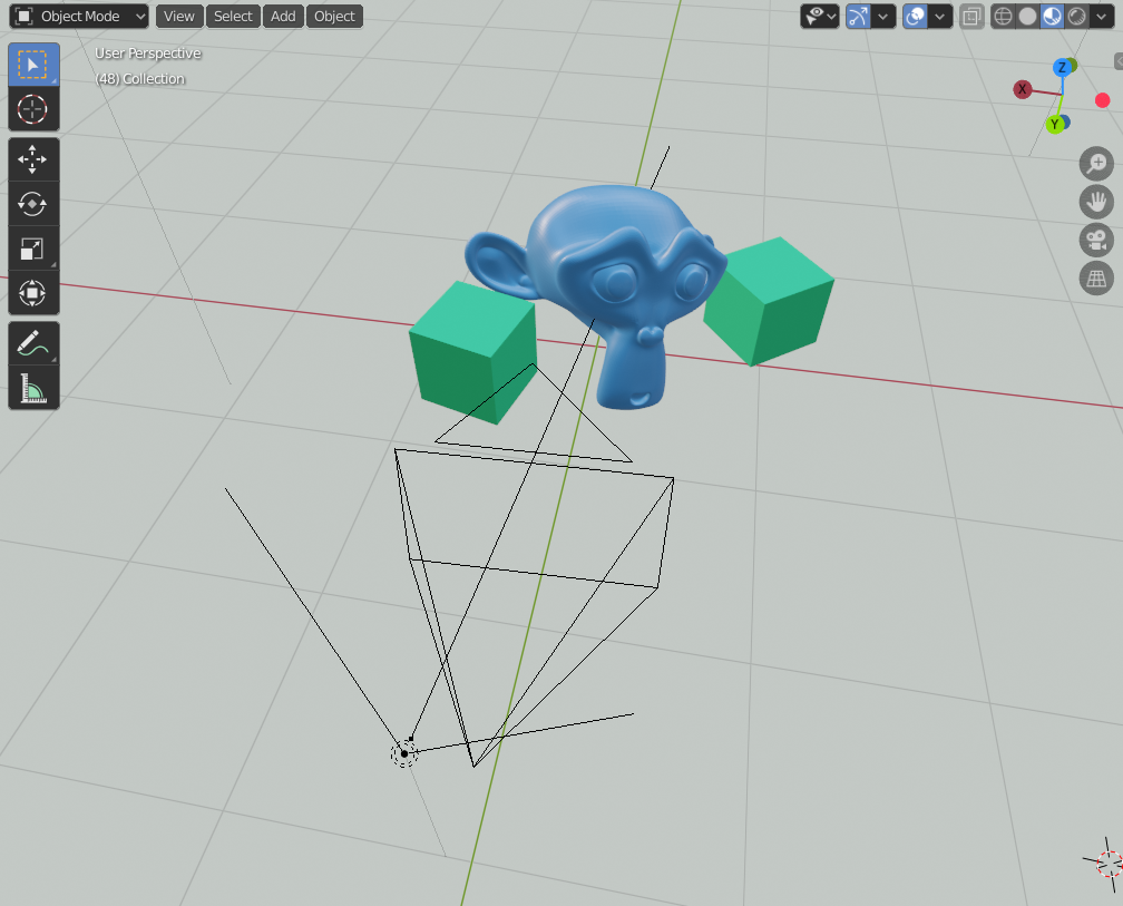
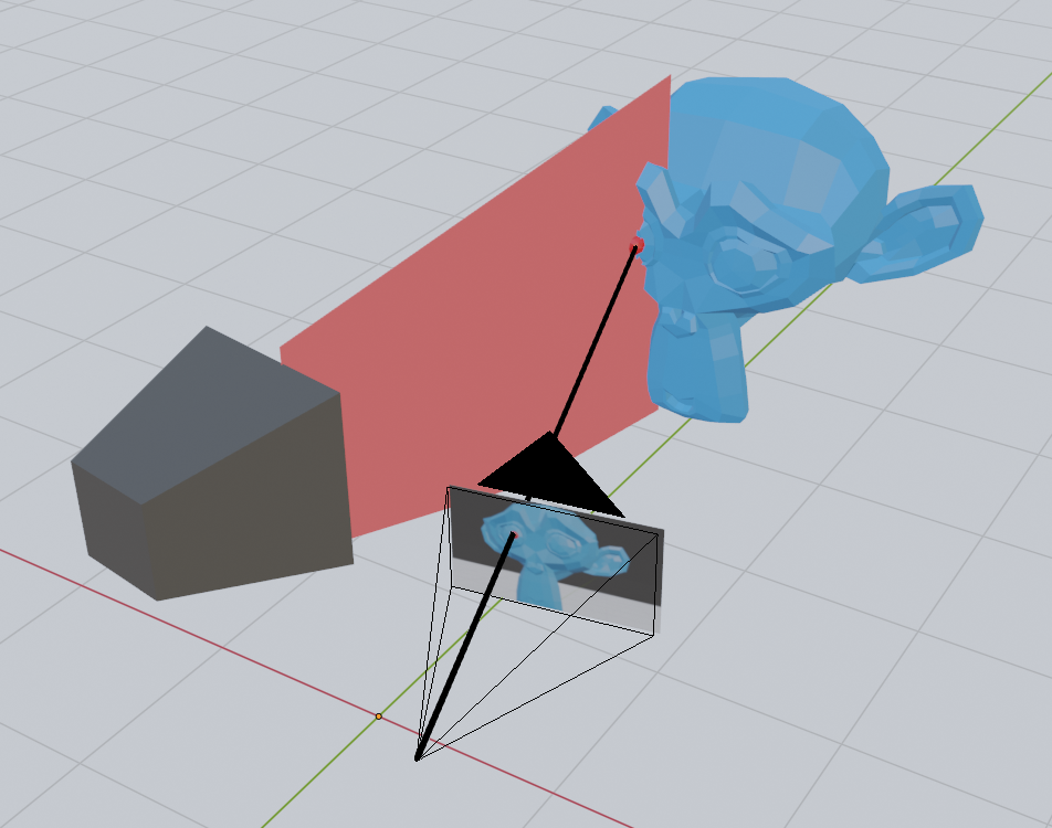
Setting up a basic projector and camera in Blender
The camera is just a regular Blender camera. The projector is made from a light with an image as color input.
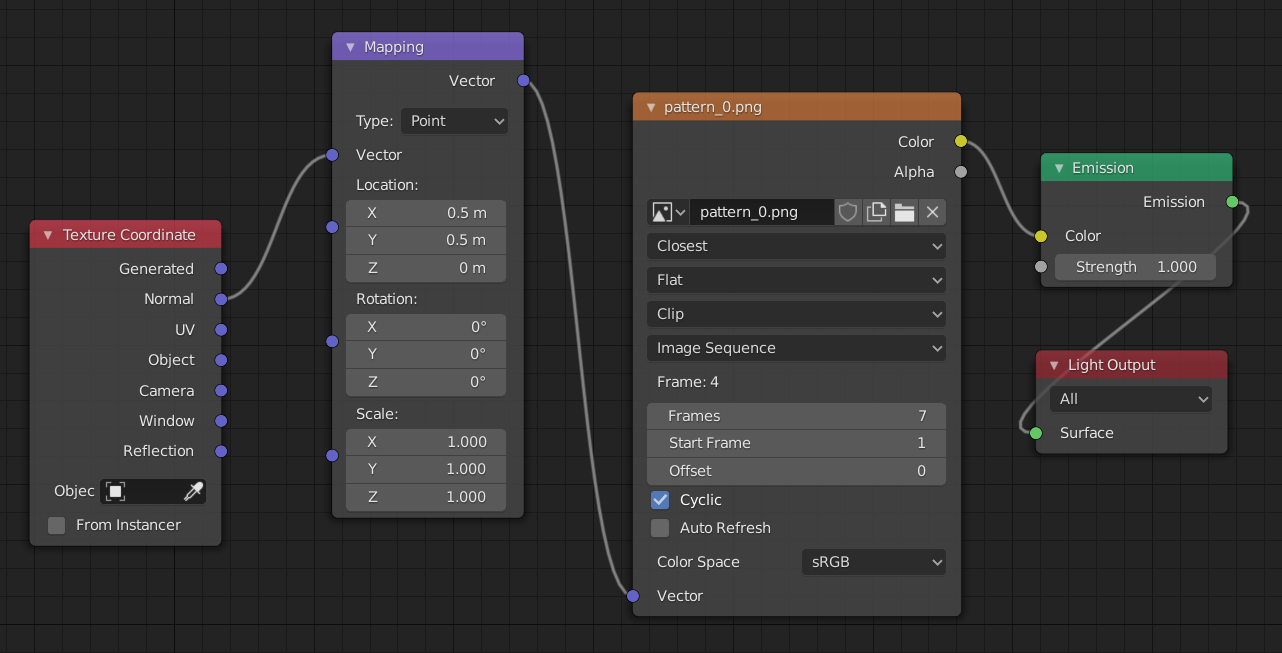
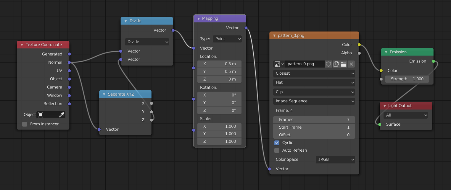
The image input to the light is be done with Blender’s node system by connecting an emission node to the light output and an image node to the emission color. The vector input of the image, which determines which pixel of the image are chosen need to be set to the normal of the texture coordinate:
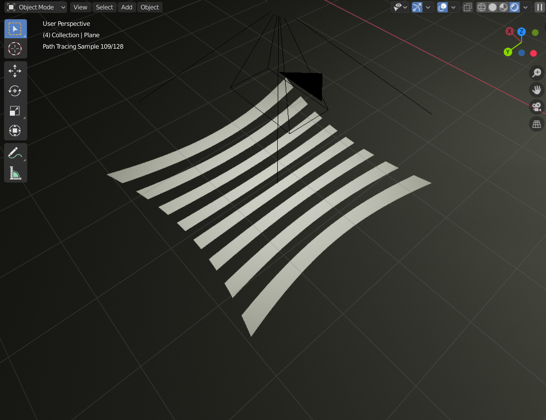
However, the projection comes out a bit distorted. Here it is shown projecting directly down on a plane:
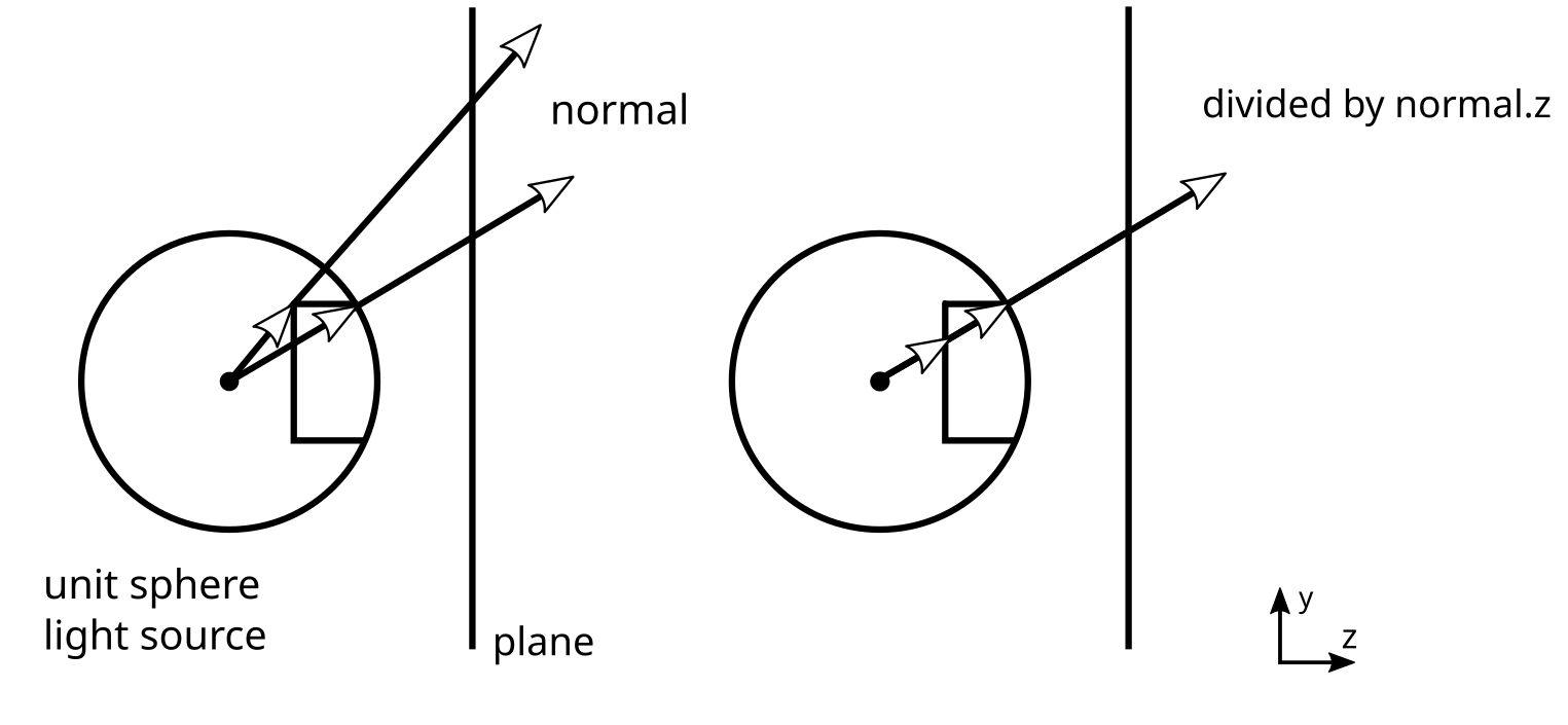
This issue occurs because the normals are projected from a unit sphere. If you draw a line across a unit sphere for a given y-value and look at how they will be projected onto a plane screen, you will notice that the rays that hit the plane are at different y-coordinates on the plane. This is because they travel different distances before hitting the plane. To compensate for this, we can divide the normal of a ray hitting the plane by its z-value, which will give the rays the proper y-value in terms of what we want for the texture coordinates:
In our node setup in Blender, the division by z can be achieved by a vector separation node and a vector division operation:
And in turn get something more like what we would expect from a real projector:
Of course, a real projector would have a lens with some defocus and distortion. The projector I made in Blender is closer to an ideal pinhole projector: the projector equivalent of a pinhole camera. A perfect pinhole projector is okay for this project, since I just want something that is easy to work with to learn how structured light works - not how to solve all its real-life challenges.
The idea behind structured light
The way structured light enables robots to see in 3D is by taking advantage of the offset and angle between the camera and projector. This is similar to how our eyes make us able to see in 3D with stereo vision, which is also used in a number of 3D cameras.
Stereo vision works by taking one image each from two regular cameras and finding common features in both. If you can identify the same point in both images, you have enough information to determine the position of that point. At least relative to the camera. Once a point is found in both images in a digital stereo camera, you have the pixel coordinate on both images. To find the 3D point, you can just draw a line from the focal point of each camera through this pixel coordinate and see where they intersect - or where they are closest to intersecting.
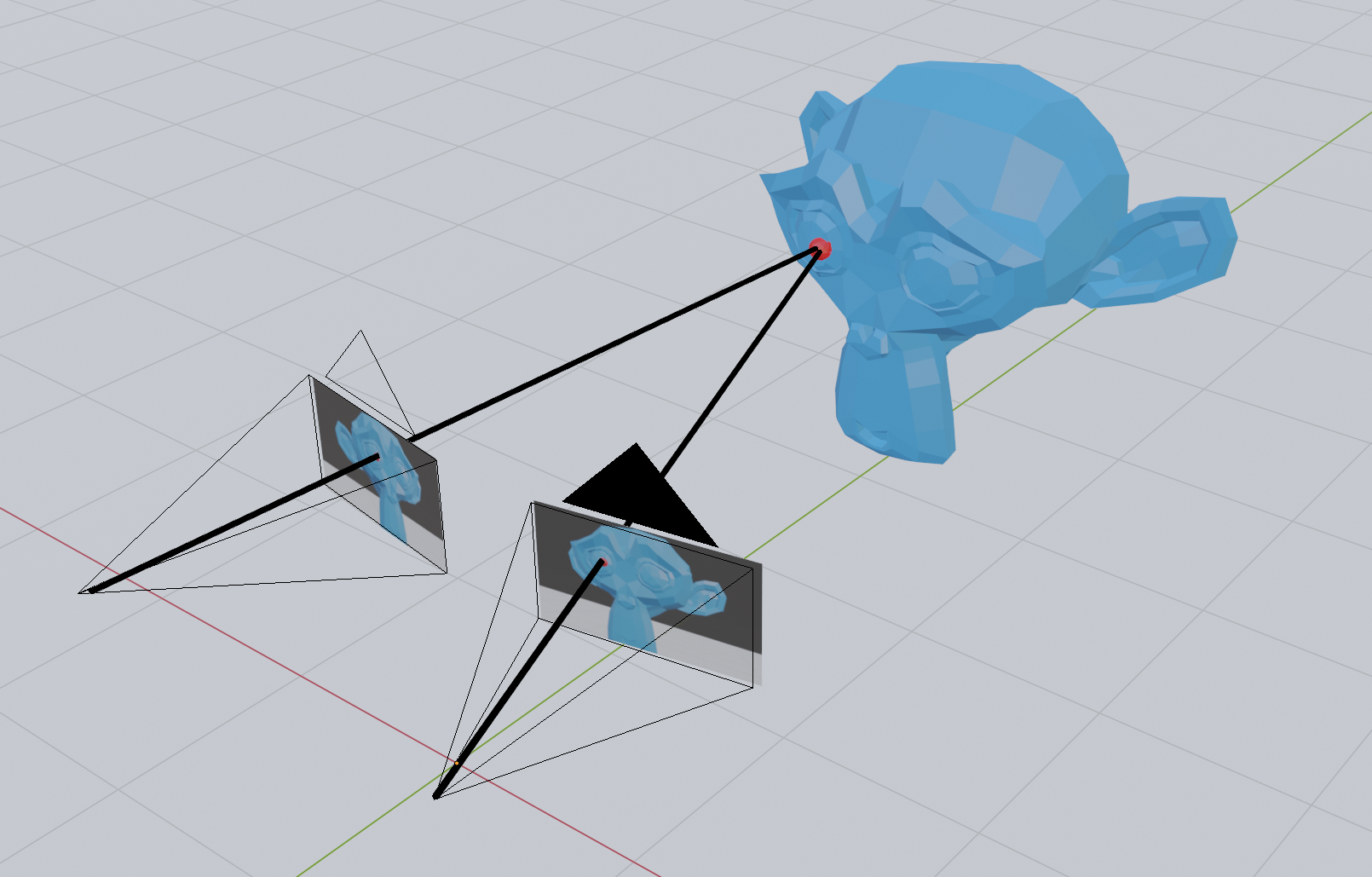
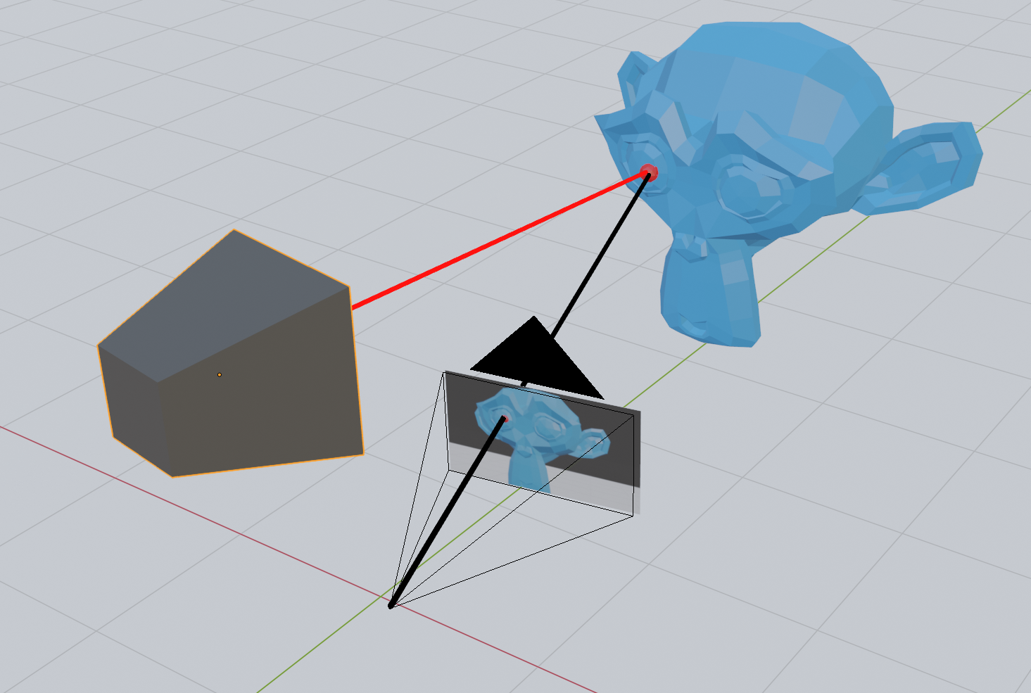
In structured light, one of the cameras is replaced by a projector. This allows us to skip the step where we detect common points in the two images, since we can light up a single point with the projector and detect only that in the camera.
However, emitting light on each point this way will take a lot of time, since you would need to take one image for each pixel on the projector. With about two million pixels in the image, we are talking about hours of imaging with a camera capable of recording at 60 FPS. Instead, we can choose to light the scene with a few clever patterns that make use of some geometrical facts about our scene.
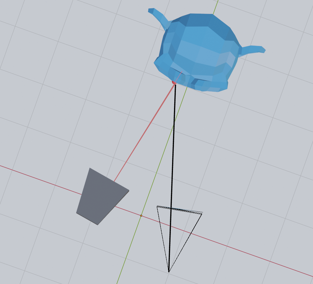
First of all, if we light the scene with horizontal lines, we may notice something peculiar when looking at the scene from the camera:
Now compare this with vertical lines:
Notice how the horizontal lines stay in the same place regardless of the position of the monkey mesh? However, the pixel position of the vertical lines changes depending on the position of the monkey. I will try to get back to the details of why this is in a later post, but the short story is that the horizontal lines do not move because the offset between the camera and projector is itself horizontal. Every horizontal line on the projector corresponds to a so-called epipolar line on the camera.
Based on this observation, we will for now just make the assumption that horizontal lines provide us with no information about the depth of the object we are imaging, while vertical lines do. In other words, it appears as if the only interesting property we need from the projector is the x position of the pixel. With the x-coordinate on the projector, we are able to create a plane that we can intersect with the camera line. The information that we get from the y-coordinate of the projector pixel must be already be contained in the y-coordinate of the camera pixel that we already have.
A line-plane intersection strategy
Since there is apparently no additional information in the y-coordinate of the projector pixel, we can find the 3D position of a point seen in the camera by intersecting the line from the camera pixel with the plane corresponding to an x-coordinate on the projector.
This means that given a pixel on the camera, all we need is some way to use the color of that pixel to determine the x-coordinate on the projector. With the x-coordinate on the projector, we are able to create a plane that we can intersect with the camera line.
The binary code patterns
There are a number of ways of encoding the x-coordinate of the projector in the pixel of the image. If we were looking at a completely white scene, we could use the color of the projector pixel to code for a specific x-coordinate. However, with colored objects in the scene, we might lose some information if the color is not projected back to us properly. We can also take two images and use the diff to encode the information we need, but again this might be hard with colors if the objects in the scene completely absorb the colored light we use for encoding.
A third option is to take multiple images with several completely black and white patterns. The simplest option is perhaps to use a binary pattern, which when read back can be interpreted as the x-coordinate on the projector.
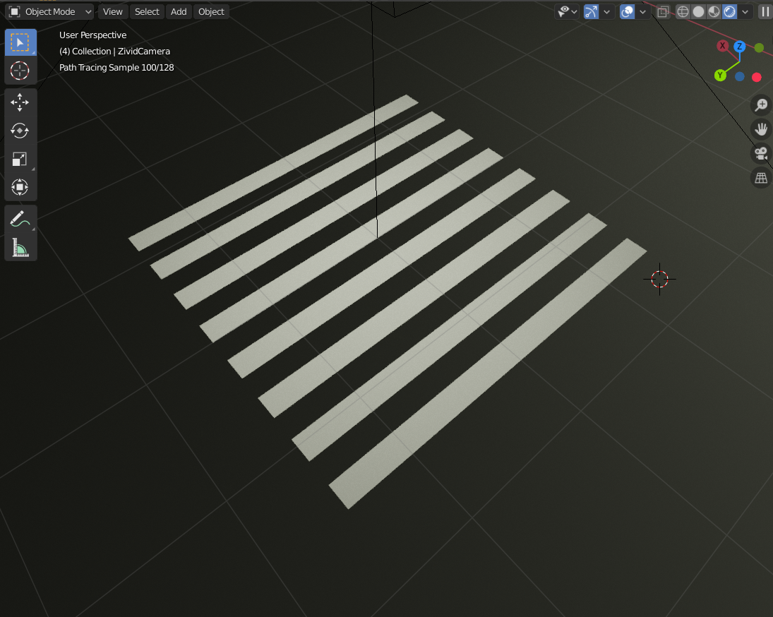
There are a number of patterns that can be used for structured light imaging with different benefits and drawbacks. For this project, I will just stick with the one I found simplest to understand, namely the binary code patterns. They consist of seven images with black and white areas:


When we take images of the scene with these patterns projected onto it, we can see which parts of the scene are hit with light from which parts of the projector. For instance, in this image, we know that the parts with light on them are coming from the right half of the projector, with the light on.
The binary code for a pixel in image is found by first calculating the minimum and maximum value for the same pixel across all images. Then we compare the pixel value of a given image with the average of the minimum and maximum value. If it is larger, we give this pixel the value one.
The pixel value is given as the grey value of the pixel, which is the average of the red, green and blue channels:
To perform these calculations on the images, we could use most image processing frameworks. Since I have been wanting to explore Halide for some time, I decided to go with that. Halide is a C++ framework that allows you to pretty much straightforwardly express the algorithms you want to implement, and then leave it to the framework to dispatch the calculations to the CPU or GPU in a reasonable order.
Decoding the patterns with Halide
In Halide, we first load the input images into one big buffer using its image helper functions:
#include <Halide.h>
#include <halide_image_io.h>

using std::string;
using std::vector;

using namespace Halide;
using namespace Halide::Tools;

Buffer<uint8_t> loadImages(vector<string> filenames)
{
    // see the repository for the full implementation
}

int main()
{
    const vector<string> filenames {
        "images/suzanne0001.png",
        "images/suzanne0002.png",
        "images/suzanne0003.png",
        "images/suzanne0004.png",
        "images/suzanne0005.png",
        "images/suzanne0006.png",
        "images/suzanne0007.png"
    };
    const auto input = loadImages(filenames);

    // TODO ...
}
Calculating the binary values is done by using a Halide reduction domain, RDom,
which allows us to perform a reduction across slices to find the minimum and maximum value
across all images.
We then compare the gray value of each image with the average of the minimum and maximum to obtain
the pixel value.
Func binaryEncode(Buffer<uint8_t> input)
{
    Func maxValue;
    Func minValue;
    Func gray;
    Func pixelValue;
    const auto rdom = RDom(0, 7);
    minValue(x, y) = 1.0f;
    maxValue(x, y) = 0.0f;
    gray(x, y, i) = 0.333f * input(x, y, 0, i) / 255.0f + 0.333f * input(x, y, 1, i) / 255.0f + 0.333f * input(x, y, 2, i) / 255.0f;
    minValue(x, y) = min(minValue(x, y), gray(x, y, rdom));
    maxValue(x, y) = max(maxValue(x, y), gray(x, y, rdom));
    pixelValue(x, y, i) = cast<float>(gray(x, y, i) > (maxValue(x, y) + minValue(x, y)) / 2.0f);
    return pixelValue;
}
We then write these values to disk as images using the following save function. The values are all clamped to [0, 1]
void saveImages(Func result, size_t width, size_t height, size_t imageCount, const string& basename)
{
    // see the repository for the full implementation
}

int main()
{
    const vector<string> filenames { /* ... */ };
    const auto input = loadImages(filenames);
    const auto encoded = binaryEncode(input);
    saveImages(encoded, input.width(), input.height(), input.extent(3), "pixelValue");
}
Which gives us the following results:
![]()
![]()
![]()
![]()
![]()
![]()
![]()
Turning the patterns into the projector x-coordinate is done by multiplying the pixel value with $2^{7-i}$ to weight the different images in a binary fashion. A light pixel in the first image is thereby worth 128, the second image 64, the third 32, and so on: summing up the value in each image. Finally, we divide by the highest value (in our case 128) and normalize to get values in the range [-1, 1]:
Func calculateProjectorX(Func pixelValue) {
    Func pixelValueWeighted;
    pixelValueWeighted(x, y, i) = pixelValue(x, y, i) * pow(2.0f, 7 - i - 1);
    const auto rdom = RDom(0, 7);
    Func accumulated;
    accumulated(x, y) = 0.0f;
    accumulated(x, y) = accumulated(x, y) + pixelValueWeighted(x, y, rdom);
    Func projectorNormalizedX;
    projectorNormalizedX(x, y) = 2.0f * accumulated(x, y) / 128.0f - 1.0f;
    return projectorNormalizedX;
}

int main()
{
    // ...
    const auto input = loadImages(filenames);

    const auto encoded = binaryEncode(input);
    saveImages(encoded, input.width(), input.height(), input.extent(3), "pixel-value");

    const auto projectorX = calculateProjectorX(encoded);
    saveImage((projectorX(x, y) + 1.0f) / 2.0f, input.width(), input.height(), "projector-x");
}
This results in the following image:
We see that the patterns are not overlapping properly and we get a few black lines in the image, but overall this is good enough to continue.
Going from pixels to points
To calculate the intersection between the line coming from the camera pixel with the plane corresponding to the projector x-coordinate, we first need to set up a few matrices that can take us from a pixel to a point. For this purpose, I will use the conventional 4x4 matrices used in computer graphics. Thankfully, these are pretty easy to set up using existing linear algebra libraries such as Eigen and glm.
In addition, Eigen supports adding custom types, which enables us to combine Eigen matrices with Halide expressions. I have therefore set up the following types and a small conversion function to takes up from a regular Eigen matrix with floats to an Eigen matrix with Halide expressions:
using Vector4h = Matrix<Halide::Expr, 4, 1>;
using Matrix4h = Matrix<Halide::Expr, 4, 4>;
using Translation3h = Translation<Halide::Expr, 3>;

Matrix4h convert(const Matrix4f& m)
{
    Matrix4h result;
    result << m(0, 0), m(0, 1), /* ... */, m(3, 3);
    return result;
}
Setting up the matrices is then pretty straightforward using the existing functionality of Eigen and glm:
Matrix4h createInverseTranslation()
{
    const auto offset = -0.2;
    const auto translation = Translation3f(Vector3f(offset, 0.0, 0.0));
    const auto inverseTranslationF = translation.inverse();
    const auto inverseTranslation = convert(Affine3f(inverseTranslationF).matrix());
    return inverseTranslation;
}

Matrix4h createInverseRotation()
{
    const auto angle = -10.0 / 180.0 * M_PI;

    const auto rotation = AngleAxisf(angle, Vector3f(0.0, 1.0, 0.0));
    const auto inverseRotationF = rotation.inverse();
    const auto inverseRotation = convert(Affine3f(inverseRotationF).matrix());
    return inverseRotation;
}

Matrix4h createInverseProjection()
{
    const float aspect = 1920.0 / 1080.0;
    const float fovx = 53.0;
    const float fovy = fovx * (1.0 / aspect) * (M_PI / 180.0);
    const float near = 0.1;
    const float far = 100.0;
    const auto projection = glm::perspective(fovy, aspect, near, far);
    const auto inverseProjectionF = glm::inverse(projection);
    const Matrix4h inverseProjection = convert(inverseProjectionF);
    return inverseProjection;
}
I say straightforward, but I probably spent an entire day before I realized that Blender stores the field of view in the largest direction, which in our case is the width (or x-direction). The glm library, on the other hand, expects the field of view in y-direction.
Note that I have only create one projection matrix. This is because I have set up the projector and camera to share the same field of view to make things easier. Or to be honest, because I did not bother to find a simple way to control the projector field of view in Blender - instead I just adjusted the camera field of view until the two were aligned.
With the matrices in place, we can create functions to unproject camera pixels and projector pixels. I decided to put the origin in the projector position:
int main()
{
    // ...
    const auto inverseTranslation = createInverseTranslation();
    const auto inverseRotation = createInverseRotation();
    const auto inverseProjection = createInverseProjection();
    const auto unprojectCamera = [=](Vector4h nCam) {
        Vector4h pCam = inverseProjection * nCam;
        pCam = pCam / pCam(3, 0);

        Vector4h pPro = inverseTranslation * inverseRotation * pCam;
        return pPro;
    };

    const auto unprojectProjector = [=](Vector4h nPro) {
        Vector4h pPro = inverseProjection * nPro;
        pPro = pPro / pPro(3, 0);
        return pPro;
    };
}
Intersecting camera rays with projector planes
Now that we are able to go from camera pixels to points in 3D space, we can create a line through our camera pixel. We of course do not know the z-value of our pixel, but by guessing two values and pulling a line through the corresponding points we get our camera line:
template<typename F>
Vector4h findCameraLine(F unprojectCamera, size_t width, size_t height)
{
    const Expr nx = 2.0f * cast<float>(x) / float(width) - 1.0f;
    const Expr ny = 2.0f * (1.0f - cast<float>(y) / float(height)) - 1.0f;
    const Vector4h normalCam1 { { nx }, { ny }, { 0.1f }, { 1.0f } };
    const Vector4h normalCam2 { { nx }, { ny }, { 0.7f }, { 1.0f } };
    const Vector4h pCam1 = unprojectCamera(normalCam1);
    const Vector4h pCam2 = unprojectCamera(normalCam2);

    const Vector4h lCam = pCam2 - pCam1;
    return lCam;
}

int main()
{
    // ...
    const auto [cameraPosition1, cameraLine] = findCameraLine(unprojectCamera, input.width(), input.height());
}
Since the projector is in origin, we just need one point to create a line. The value for z is just arbitrary:
template<typename F>
Vector4h findProjectorLine(F unprojectProjector, Expr projectorX)
{
    const Vector4h normalPro {
        { projectorX }, { 0.0f }, { 0.7f }, { 1.0f }
    };
    const Vector4h lPro = unprojectProjector(normalPro);
    return lPro;
}

int main()
{
    const auto cameraLine = findCameraLine(unprojectCamera, input.width(), input.height());
    const auto projectorLine = findProjectorLine(unprojectProjector, projectorX(x, y));
}
But why create two lines if we want to intersect a plane based on the projector x-coordinate with the line based on the camera pixel? And why set the projector y-coordinate to zero above? Well, simply because a line-plane intersection is the same as a line-line intersection in 2D if the plane is parallel with one of the axes. And in our case, it is parallel with the y-axis.
We can therefore calculate a 2D line intersection to find where along the camera line the 3D intersection happens:
Expr intersect2D(Vector4h cameraPosition1, Vector4h cameraLine, Vector4h projectorLine)
{
    const Vector4h p = Vector4h { { 0.0f }, { 0.0f }, { 0.0f }, { 1.0f } };
    const Vector4h r = projectorLine - p;

    const Vector4h q = cameraPosition1;
    const Vector4h s = cameraLine;

    auto cross2D = [](auto a, auto b) {
    return a(0, 0) * b(2, 0) - b(0, 0) * a(2, 0);
    };

    const Expr pxr = cross2D(p, r);
    const Expr qxr = cross2D(q, r);
    const Expr qmpxr = qxr - pxr;
    const Expr rxs = cross2D(r, s);
    const Expr uCam = qmpxr / rxs;
    return uCam;
}

int main()
{
    // ...
    const auto [cameraPosition1, cameraLine] = findCameraLine(unprojectCamera, input.width(), input.height());
    const auto projectorLine = findProjectorLine(unprojectProjector, projectorX(x, y));
    const auto intersection = intersect(cameraPosition1, cameraLine, projectorLine);
}
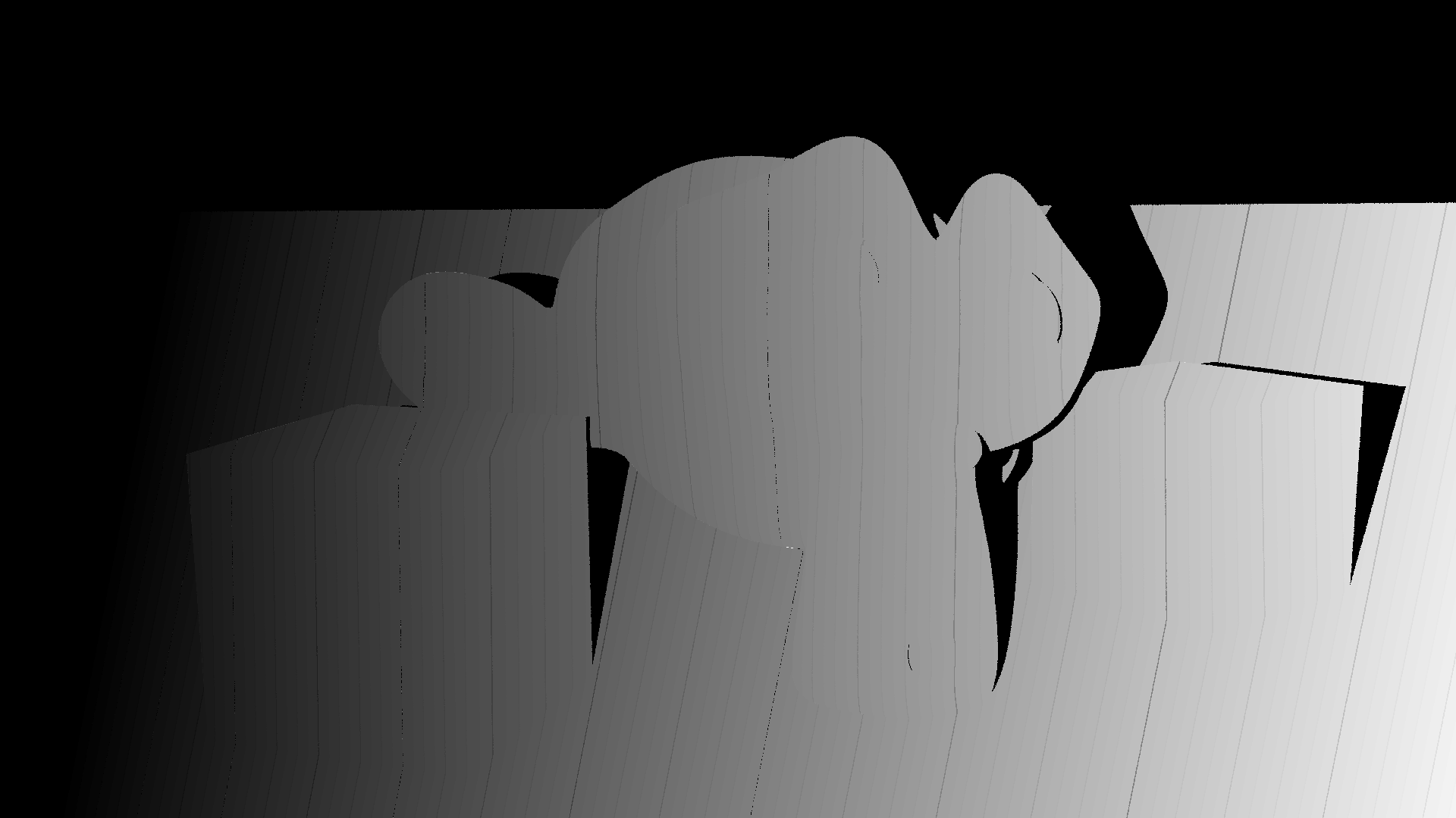
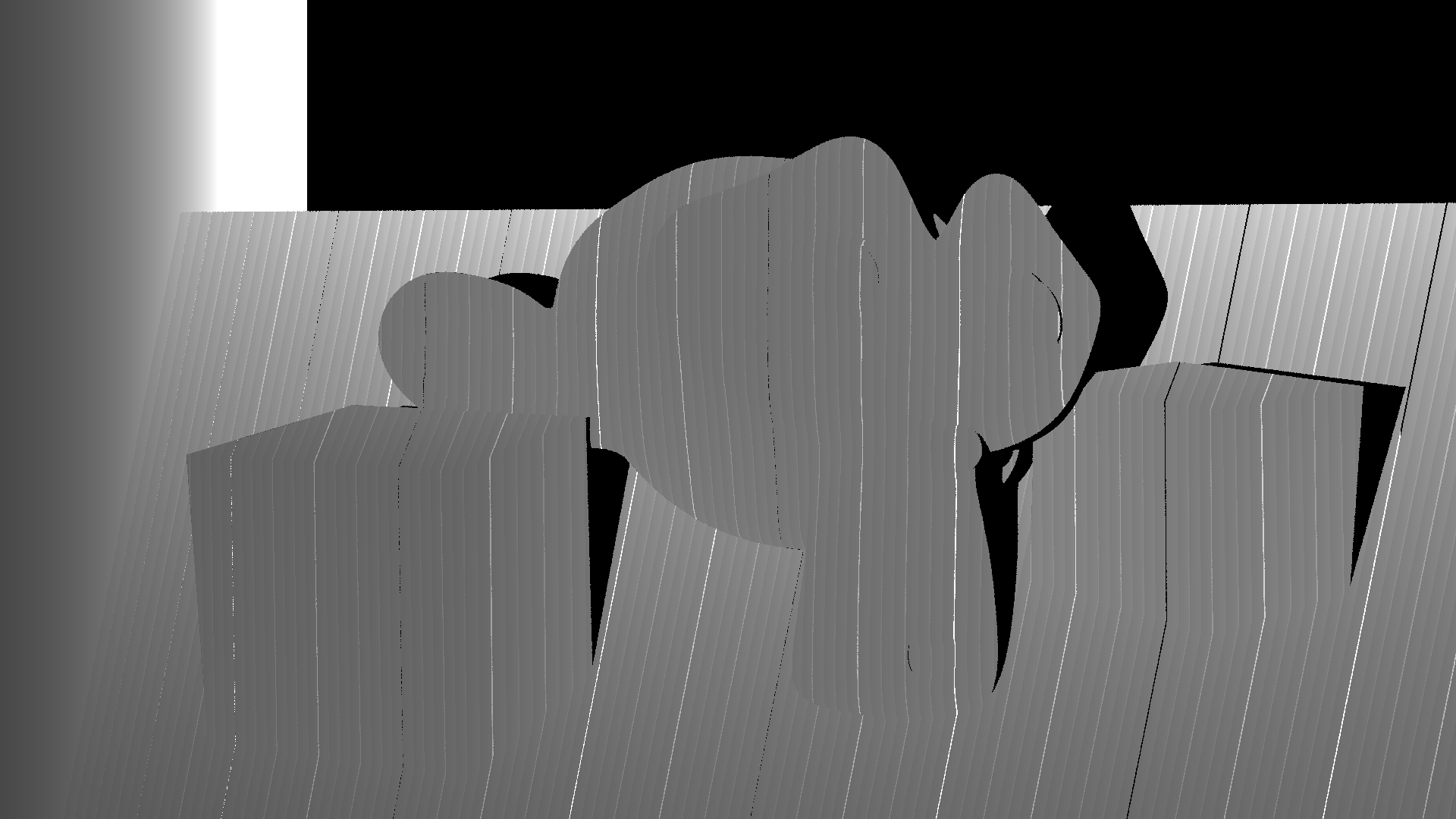
We can then save the z value to an image. Note that the z-value is negative in the matrix convention we have used and that I divide by 3.0 because I know that better reflects the distance to the objects in the scene.
int main()
{
    saveImage(-intersection(2, 0) / 3.0f, input.width(), input.height(), "intersection");
}
The resulting depth image looks as follows:
But what we want is not just the depth as an image. We want to produce a 3D model from the images. To produce the 3D model, we can create a new function where we store the x, y, and z values together with the color. The color can be calculated as the mean of the maximum and minimum color in the images. The average is between the color we would see when the projector lights the entire scene and when there is no light from the projector:
Func calculateColor(Buffer<uint8_t> input)
{
    Func minColor;
    Func maxColor;

    const auto rdom = RDom(0, 7);

    minColor(x, y, c) = 1.0f;
    minColor(x, y, c) = min(minColor(x, y, c), input(x, y, c, rdom) / 255.0f);

    maxColor(x, y, c) = 0.0f;
    maxColor(x, y, c) = max(maxColor(x, y, c), input(x, y, c, rdom) / 255.0f);

    Func color;
    color(x, y, c) = 0.5f * (minColor(x, y, c) + maxColor(x, y, c));
    return color;
}

int main()
{
    // ...
    const auto color = calculateColor(input);
}
Next, we store the intersection and color together in a new function and write this to a buffer:
int main()
{
    // ...
    Func result;
    result(x, y, c) = 0.0f;
    result(x, y, 0) = intersection(0, 0);
    result(x, y, 1) = intersection(1, 0);
    result(x, y, 2) = intersection(2, 0);
    result(x, y, 3) = color(x, y, 0);
    result(x, y, 4) = color(x, y, 1);
    result(x, y, 5) = color(x, y, 2);

    Target target = get_host_target();
    result.compile_jit(target);
    Buffer<float> output(input.width(), input.height(), 6);
    result.realize(output);
    output.copy_to_host();
}
Finally we write results to an XYZ file:
int main()
{
    // ...
    std::vector<Point> points;

    for (int j = 0; j < cpu_output.height(); j++) {
        for (int i = 0; i < cpu_output.width(); i++) {
            const auto x = cpu_output(i, j, 0);
            const auto y = cpu_output(i, j, 1);
            const auto z = cpu_output(i, j, 2);
            const auto red = cpu_output(i, j, 3);
            const auto green = cpu_output(i, j, 4);
            const auto blue = cpu_output(i, j, 5);

            if (x < -10.0f || x > 10.0f || y < -10.0f || y > 10.0f || z < -10.0f || z > 10.0f) {
                continue;
            }
            points.push_back({ x, y, z, red, green, blue });
        }
    }

    std::ofstream outFile;
    outFile.open("out.xyz");
    outFile << points.size() << "\n";
    outFile << "comment"
            << "\n";
    for (const auto& point : points) {
        outFile << point.x << " " << point.y << " " << point.z << " " << point.red
                << " " << point.green << " " << point.blue << "\n";
    }
}
The XYZ file can be loaded in a viewer, such as Ovito:
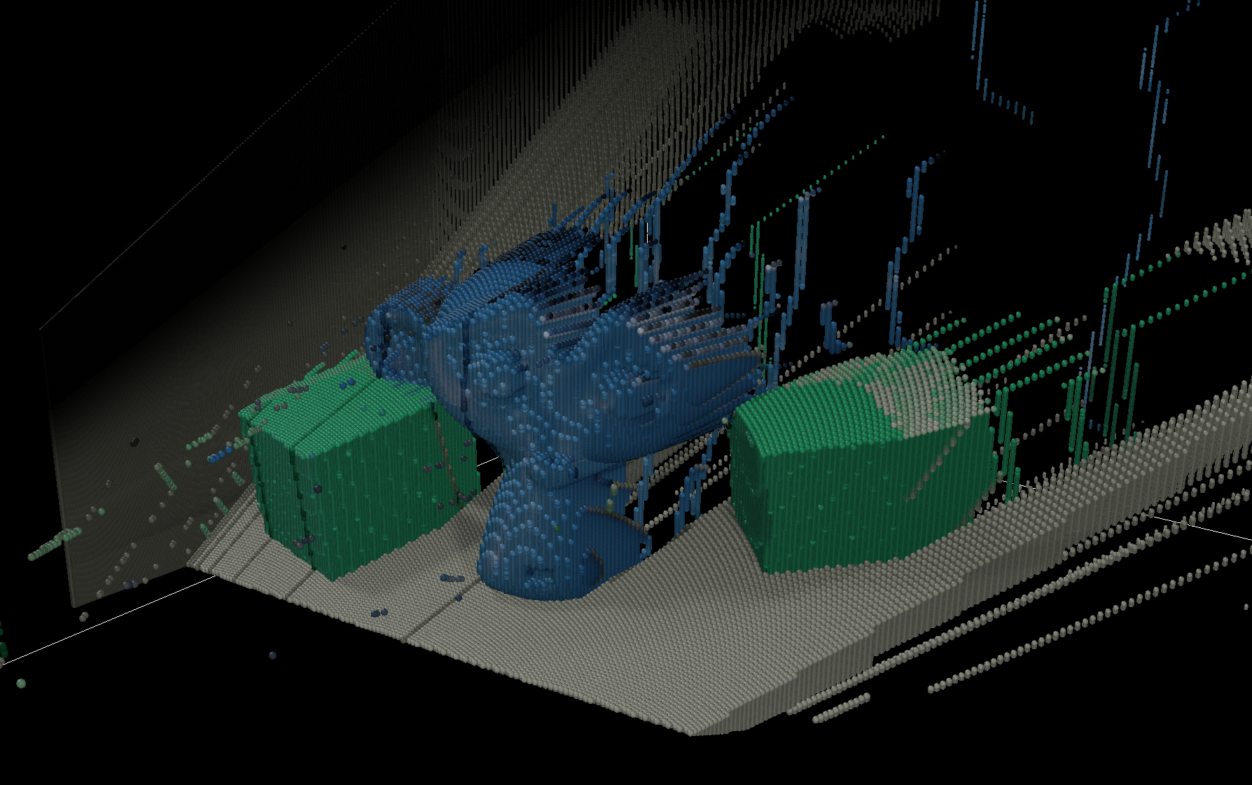
After looking at some really bad results for a day when I had the wrong matrices, I was really happy to get this on screen!
Sure, there is still a lot of noise to clean up, and weird effects such as the floor which now has a thickness, but I will address those later.
For now, I am happy with this as it is.